Whenever I deploy a Cisco UCS at a customer the question I get asked a lot is how traffic flows within the system between VMs running on the blades and FEX modules, FEX modules and Fabric Interconnects and finally how it’s uplinked to the network core.
Cisco has a range of CNA cards for UCS blades. With VIC 1280 you get 8 x 10Gb ports split between two FEX modules for redundancy. And FEX modules on their own can have up to 8 x 10Gb Fabric Interconnect facing interfaces, which can give you up to 160Gb of bandwidth per chassis. And all these numbers may sound impressive, but unless you understand how your VMs traffic flows through UCS it’s easy to make wrong assumptions on what per VM and aggregate bandwidth you can achieve. So let’s dive deep into UCS and shed some light on how VM traffic is load-balanced within the system.
UCS Hardware Components
Each Fabric Extender (FEX) has external and internal ports. External FEX ports are patched to FIs and internal ports are internally wired to the blade adapters. FEX 2204 has 4 external and 16 internal and FEX 2208 has 8 external and 32 internal ports.
External ports are connected to FIs in powers of two: 1, 2, 4 or 8 ports per FEX and form a port channel (make sure to use “Port Channel” link grouping preference under Chassis/FEX Discovery Policy). Same rule is applied to blade Virtual Interface Cards (VIC). The most common VIC 1240 and 1280 have 4 x 10Gb and 8 x 10Gb ports respectively and also form a port channel to the internal FEX ports. Every VIC adaptor is connected to both FEX modules for redundancy.

Fabric Interconnects are then patched to your network core and FC Fabric (if you have one). Whether Ethernet uplinks will be individual uplinks or port channels will depend on your network topology. For fibre uplinks the rule of thumb is to patch FI A to your FC Fabric A and FI B to FC Fabric B, which follows the common FC traffic isolation principle.
Virtual Circuits
To provide network and storage connectivity to blades you create virtual NICs and virtual HBAs on each blade. Since internally UCS uses FCoE to transfer FC frames, both vNICs and vHBAs use the same 10GbE uplinks to send and receive traffic. Worth mentioning that Cisco uses Data Center Bridging (DCB) protocol with it’s sub-protocols Priority Flow Control (PFC) and Enhanced Transmission Selection (ETS), which guarantee that FC frames have higher priority in the queue and are processed first to ensure low latency. But I digress.
UCS assigns a virtual circuit to each virtual adaptor, which is a representation of how the traffic traverses the system all the way from the VIC port to a FEX internal port, then FEX external port, FI server port and finally a FI uplink. You can trace the full path of each virtual adaptor in UCS Manager by selecting a Service Profile and viewing the VIF Paths tab.
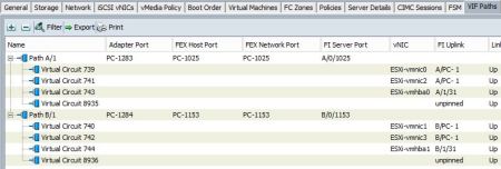
In this example we have a blade with four vNICs and two vHBAs which are split between two fabrics. All virtual adaptors on fabric A are connected through VIC port channel PC-1283 which is represented as port channel PC-1025 on the FEX A side. Then traffic leaves FEX A and reaches the Fabric Interconnect A which sends the traffic out to the network core through port channel A/PC-1.
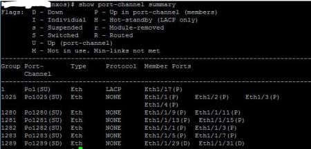
You can also get the list of port channels from the FI CLI:
# connect nxos
# show port-channel summary
Network Load Balancing
Now that we know how all components are interconnected to each other, let’s discuss the traffic flow in a typical VMware environment and how we achieve the massive network throughput that UCS provides.
As an example let’s take a look at the vSwitch where your VM Network port group is configured. vSwitch will have two uplinks – one goes to Fabric A and the other one to Fabric B for redundancy. Default load balancing policy on a vSwitch is “Route based on the originating port ID”, which essentially pins all traffic for a VM to a particular uplink. vSphere makes sure that VMs are evenly distributed between the uplinks to use all network bandwidth available.
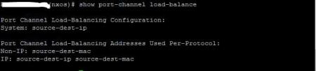
From each uplink (or vNIC in UCS world) traffic is forwarded through an adapter port channel to a FEX, then to a Fabric Interconnect and leaves UCS from a FI uplink. Within UCS traffic is distributed between port channel members using source/destination IP hash algorithm. Which is even more granular and is capable of very efficient traffic distribution between all members of a port channel all the way up to your network core.
If you look at the vSwitch you’ll see that with UCS each uplink shows the maximum available bandwidth from vNIC and is not limited to a port channel member speed of 10Gb. Why is this so powerful? Because with UCS you don’t need to slice adapter’s available bandwidth between different types of traffic. Even though you provision multiple vNICs and vHBAs for the vSphere hosts, UCS uses the same port channel links (20Gb in the example below) from the VIC adapter to transfer all traffic and takes care of load balancing for you.

You may legitimately ask, if UCS uses the same pipe to transfer all data regardless of which vSwitch uplink is being used, then how can I make sure that different types of traffic, such as vMotion, storage, VM traffic, replication, etc, do not compete for the same pipe? First you need to ask yourself if you can saturate that much bandwidth with your workloads. If the answer is yes, then you can use another great feature available in UCS, which is QoS. QoS lets you assign a minimum available bandwidth guarantee on a per vNIC/vHBA basis. But that’s a topic for another blog post.
References
In this post I tried to summarise the logic behind UCS traffic distribution. If you want to dig deeper in UCS network architecture, then there’re a lot of great bloggers out there. I would like to call out the following authors:
- Brad Hedlund – if you want to better understand overall UCS architecture and network best practices, Bred has a great series of videos:
- Colin Lynch (UCSguru) – this blog is dedicated specifically to UCS. If you want to know more about the virtual circuits, I would recommend these two blog posts:
- Matthew Oswalt – Keeping It Classless is a blog which is geared more towards DevOps, but also has a few UCS articles, I found this one particularly useful:
Tags: adapter, adaptor, Data Center Bridging, DCB, distribution, Enchanced Transmission Selection, ETC, Fabric Externder, Fabric Interconnect, FC, FEX, FI, fiber channel, fibre, load balancing, network, PFC, port channel, priority, Priority Flow Control, queue, redundancy, traffic, UCS, Unified Computing System, uplink, vHBA, VIC, VIF, virtual circuit, Virtual Interface Card, vmware, vNIC, vSphere, vSwitch

December 15, 2016 at 12:21 pm |
Hello,
Interesting article.
But i have question, i need to implement load balance Leaf A and Leaf B. I understand with configuration on Guest OS (Vmware or Baremetal). But i still not understand with configuration attribute on FI or Leaf.
In my test, i can successfully ping from guest os (in baremetall or vmware) on gateway, but then i check on each leaf, i just found arp on Leaf A but not found in Leaf B (Leaf B doest receave arp table). But Leaf B got mac address table received from Leaf A. So i assume the load balancing doesnt work.
My topologi like :
Cluster
Leaf A Leaf B
| |
| |
eth0 Blade Server eth1
Blade server using ip gateway from interface vlan leaf A and leaf B (same address).
I create interface teaming from blade server, with each interface pointing to leaf A and Leaf B. I just set in UCS adapter to:
eth0 : AB
eth1 : BA
Thanks.
May 31, 2017 at 12:58 am |
Hi Randy, it’s not clear from your question what your network topology is. If you can share a detailed diagram of what you’re trying to achieve, I might be able to help.