Posts Tagged ‘redundancy’

Load Balancing Ansible Tower Using NSX

February 1, 2020

Disclamer: this configuration is not validated by either VMware or Red Hat. Make sure it is applicable to your use case and thoroughly test before implementing in production.

Overview

If you landed on this page I trust you already know what Ansible is. It’s a great configuration management tool centred around using YAML to describe the desired state configuration of your various infrastructure components. This desired state is captured in what Ansible calls playbooks, which once written, can then be used in a repeatable way to deploy brand new components or enforce configuration on already deployed ones.

Ansible can be installed and used from CLI, which is usually a good starting point. If you have multiple people using Ansible in your organization, you can also deploy AWX. It’s a free GUI add-on to Ansible, which makes managing concurrent user access to Ansible easier, by adding projects, schedules and credentials management. On top of that there is Ansible Tower. Ansible Tower is a paid version of AWX and gives you additional enterprise features and services like clustering, product support, validated upgrade paths, etc. In this article we will be focusing on Ansible Tower version of the product.

Also worth mentioning that this configuration will be based on Ansible Tower cluster feature, which lets you run all nodes as active/active. Prior to version 3.1 it was called redundancy and worked only in active/passive mode. Redundancy feature is deprecated and is outside the scope of this blog post.

Topology

Deploying multiple Ansible Tower nodes in a cluster already gives you redundancy. If one of the nodes fails you can connect to another node, by just changing your browser URL. The benefit of having a load balancer is that you have one URL you can hit and if a node goes down, such situation is handled by load balancer automatically.

In this example we will be deploying a VMware NSX load-balancer in the following topology:

Configuration

Deploying an NSX load-balancer for HTTPS port 443 is simple, you can find numerous examples of how to create application profiles, monitors, pools and VIPs in official VMware documentation or out on the Internet. But with Ansible there’s one catch. If you try to use the default HTTPS monitor that NSX load balancer comes with, you will find HTTP 400 code in Ansible nginx logs:

10.20.30.40 - - [20/Jan/2020:04:50:19 +0000] "GET / HTTP/1.0" 400 3786 "-" "-" "-"
10.20.30.40 - - [20/Jan/2020:04:50:24 +0000] "GET / HTTP/1.0" 400 3786 "-" "-" "-"
10.20.30.40 - - [20/Jan/2020:04:50:29 +0000] "GET / HTTP/1.0" 400 3786 "-" "-" "-"

And an error in NSX load balancer health check:

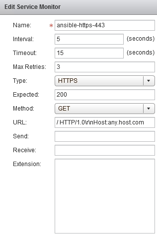
As it turns out, when you make a HTTP request to Ansible Tower, specifying HTTP “Host” header is a requirement. Host header simply contains the hostname of the server you’re making a request to. Browsers add this header automatically, that’s why you’re not going to see any errors, when accessing Ansible Tower Using Firefox or Chrome. But NSX doesn’t add this header to the monitor checks by default, which makes Ansible Tower upset.

Here is the trick you need to do to make Tower happy:

Now nginx logs show success code 200:

10.20.30.40 - - [21/Jan/2020:22:54:42 +0000] "GET / HTTP/1.0" 200 11337 "-" "-" "-"
10.20.30.40 - - [21/Jan/2020:22:54:47 +0000] "GET / HTTP/1.0" 200 11337 "-" "-" "-"
10.20.30.40 - - [21/Jan/2020:22:54:52 +0000] "GET / HTTP/1.0" 200 11337 "-" "-" "-"

Load balancer health check is successful:

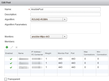
And pool members are up and reachable:

Note: technically the host header should contain the hostname of the Tower node we’re making a health check on. But since NSX monitor is configured per pool and not per pool member, we have to use a fake hostname “any.host.com” as a workaround. When I was testing it, Tower didn’t complain.

Reference

Even though I said that the rest of the load-balancer configuration is standard, I still think having screenshots for reference is helpful if you need to validate configuration. So find the full list of settings below.

Screenshot 1: Application Profile

Screenshot 2: Service Monitor

Screenshot 3: Pool

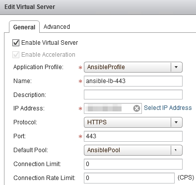
Screenshot 4: Virtual Server

How Admission Control Really Works

May 2, 2016

confusionThere is a moment in every vSphere admin’s life when he faces vSphere Admission Control. Quite often this moment is not the most pleasant one. In one of my previous posts I talked about some of the common issues that Admission Control may cause and how to avoid them. And quite frankly Admission Control seems to do more harm than good in most vSphere environments.

Admission Control is a vSphere feature that is built to make sure that VMs with reservations can be restarted in a cluster if one of the cluster hosts fails. “Reservations” is the key word here. There is a common belief that Admission Control protects all other VMs as well, but that’s not true.

Let me go through all three vSphere Admission Control policies and explain why you’re better of disabling Admission Control altogether, as all of these policies give you little to no benefit.

Host failures cluster tolerates

This policy is the default when you deploy a vSphere cluster and policy which causes the most issues. “Host failures cluster tolerates” uses slots to determine if a VM is allowed to be powered on in a cluster. Depending on whether VM has CPU and memory reservations configured it can use one or more slots.

Slot Size

To determine the total number of slots for a cluster, Admission Control uses slot size. Slot size is either the default 32MHz and 128MB of RAM (for vSphere 6) or if you have VMs in the cluster configured with reservations, then the slot size will be calculated based on the maximum CPU/memory reservation. So say if you have 100 VMs, 98 of which have no reservations, one VM has 2 vCPUs and 8GB of memory reserved and another VM has 4 vCPUs and 4GB of memory reserved, then the slot size will jump from 32MHz / 128MB to 4 vCPUs / 8GB of memory. If you have 2.0 GHz CPUs on your hosts, the 4 vCPU reservation will be an equivalent of 8.0 GHz.

Total Number of Slots

Now that we know the slot size, which happens to be 8.0 GHz and 8GB of memory, we can calculate the total number of slots in the cluster. If you have 2 x 8 core CPUs and 256GB of RAM in each of 4 ESXi hosts, then your total amount of resources is 16 cores x 2.0 GHz x 4 hosts = 128 GHz and 256GB x 4 hosts = 1TB of RAM. If your slot size is 4 vCPUs and 8GB of RAM, you get 64 vCPUs / 4 vCPUs = 16 slots (you’ll get more for memory, but the least common denominator has to be used).

total_slots

Practical Use

Now if you configure to tolerate one host failure, you have to subtract four slots from the total number. Every VM, even if it doesn’t have reservations takes up one slot. And as a result you can power on maximum 12 VMs on your cluster. How does that sound?

Such incredibly restrictive behaviour is the reason why almost no one uses it in production. Unless it’s left there by default. You can manually change the slot size, but I have no knowledge of an approach one would use to determine the slot size. That’s the policy number one.

Percentage of cluster resources reserved as failover spare capacity

This is the second policy, which is commonly recommended by most to use instead of the restrictive “Host failures cluster tolerates”. This policy uses percentage-based instead of the slot-based admission.

It’s much more straightforward, you simply specify the percentage of resources you want to reserve. For example if you have four hosts in a cluster the common belief is that if you specify 25% of CPU and memory, they’ll be reserved to restart VMs in case one of the hosts fail. But it won’t. Here’s the reason why.

When calculating amount of free resources in a cluster, Admission Control takes into account only VM reservations and memory overhead. If you have no VMs with reservations in your cluster then HA will be showing close to 99% of free resources even if you’re running 200 VMs.

failover_capacity

For instance, if all of your VMs have 4 vCPUs and 8GB of RAM, then memory overhead would be 60.67MB per VM. For 300 VMs it’s roughly 18GB. If you have two VMs with reservations, say one VM with 2 vCPUs / 4GB of RAM and another VM with 4 vCPUs / 2GB of RAM, then you’ll need to add up your reservations as well.

So if we consider memory, it’s 18GB + 4GB + 2GB = 24GB. If you have the total of 1TB of RAM in your cluster, Admission Control will consider 97% of your memory resources being free.

For such approach to work you’d need to configure reservations on 100% of your VMs. Which obviously no one would do. So that’s the policy number two.

Specify failover hosts

This is the third policy, which typically is the least recommended, because it dedicates a host (or multiple hosts) specifically just for failover. You cannot run VMs on such hosts. If you try to vMotion a VM to it, you’ll get an error.

failover_host

In my opinion, this policy would actually be the most useful for reserving cluster resources. You want to have N+1 redundancy, then reserve it. This policy does exactly that.

Conclusion

When it comes to vSphere Admission Control, everyone knows that “Host failures cluster tolerates” policy uses slot-based admission and is better to be avoided.

There’s a common misconception, though, that “Percentage of cluster resources reserved as failover spare capacity” is more useful and can reserve CPU and memory capacity for host failover. But in reality it’ll let you run as many VMs as you want and utilize all of your cluster resources, except for the tiny amount of CPU and memory for a handful of VMs with reservations you may have in your environment.

If you want to reserve failover capacity in your cluster, either use “Specify failover hosts” policy or simply disable Admission Control and keep an eye on your cluster resource utilization manually (or using vROps) to make sure you always have room for growth.

Implications of Ignoring vSphere Admission Control

April 5, 2016

no-admissionHA Admission Control has historically been on of the lesser understood vSphere topics. It’s not intuitive how it works and what it does. As a result it’s left configured with default values in most vSphere environments. But default Admission Control setting are very restrictive and can often cause issues.

In this blog post I want to share the two most common issues with vSphere Admission Control and solutions to these issues.

Issue #1: Not being able to start a VM

Description

Probably the most common issue everyone encounters with Admission Control is when you suddenly cannot power on VMs any more. There are multiple reasons why that might happen, but most likely you’ve just configured a reservation on one of your VMs or deployed a VM from an OVA template with a pre-configured reservation. This has triggered a change in Admission Control slot size and based on the new slot size you no longer have enough slots to satisfy failover requirements.

As a result you get the following alarm in vCenter: “Insufficient vSphere HA failover resources”. And when you try to create and boot a new VM you get: “Insufficient resources to satisfy configured failover level for vSphere HA”.

admission_error

Cause

So what exactly has happened here. In my example a new VM with 4GHz of CPU and 4GB of RAM was deployed. Admission Control was set to its default “Host Failures Cluster Tolerates” policy. This policy uses slot sizes. Total amount of resources in the cluster is divided by the slot size (4GHz and 4GB in the above case) and then each VM (even if it doesn’t have a reservation) uses at least 1 slot. Once you configure a VM reservation, depending on the number of VMs in your cluster more often than not you get all slots being used straight away. As you can see based on the calculations I have 91 slots in the cluster, which have instantly been used by 165 running VMs.

slot_calculations

Solution

You can control the slot size manually and make it much smaller, such as 1GHz and 1GB of RAM. That way you’d have much more slots. The VM from my previous example would use four slots. And all other VMs which have no reservations would use less slots in total, because of a smaller slot size. But this process is manual and prone to error.

The better solution is to use “Percentage of Cluster Resources” policy, which is recommended for most environments. We’ll go over the main differences between the three available Admission Control policies after we discuss the second issue.

Issue #2: Not being able to enter Maintenance Mode

Description

It might be a corner case, but I still see it quite often. It’s when you have two hosts in a cluster (such as ROBO, DR or just a small environment) and try to put one host into maintenance mode.

The first issue you will encounter is that VMs are not automatically vMotion’ed to other hosts using DRS. You have to evacuate VMs manually.

And then once you move all VMs to the other host and put it into maintenance mode, you again can no longer power on VMs and get the same error: “Insufficient resources to satisfy configured failover level for vSphere HA”.

poweron_fail

Cause

This happens because disconnected hosts and hosts in maintenance mode are not used in Admission Control calculations. And one host is obviously not enough for failover, because if it fails, there are no other hosts to fail over to.

Solution

If you got caught up in such situation you can temporarily disable Admission Control all together until you finish maintenance. This is the reason why it’s often recommended to have at least 3 hosts in a cluster, but it can not always be justified if you have just a handful of VMs.

Alternatives to Slot Size Admission Control

There are another two Admission Control policies. First is “Specify a Failover Host”, which dedicates a host (or hosts) for failover. Such host acts as a hot standby and can run VMs only in a failover situation. This policy is ideal if you want to reserve failover resources.

And the second is “Percentage of Cluster Resources”. Resources under this policy are reserved based on the percentage of total cluster resources. If you have five hosts in your cluster you can reserve 20% of resources (which is equal to one host) for failover.

This policy uses percentage of cluster resources, instead of slot sizes, and hence doesn’t have the issues of the “Host Failures Cluster Tolerates” policy. There is a gotcha, if you add another five hosts to your cluster, you will need to change reservation to 10%, which is often overlooked.

Conclusion

“Percentage of Cluster Resources” policy is recommended to use in most cases to avoid issues with slot sizes. What is important to understand is that the goal of this policy is just to guarantee that VMs with reservations can be restarted in a host failure scenario.

If a VM has no reservations, then “Percentage of Cluster Resources” policy will use only memory overhead of this VM in its calculations. Which is probably the most confusing part about Admission Control in general. But that’s a topic for the next blog post.


Traffic Load Balancing in Cisco UCS

December 21, 2015

Whenever I deploy a Cisco UCS at a customer the question I get asked a lot is how traffic flows within the system between VMs running on the blades and FEX modules, FEX modules and Fabric Interconnects and finally how it’s uplinked to the network core.

Cisco has a range of CNA cards for UCS blades. With VIC 1280 you get 8 x 10Gb ports split between two FEX modules for redundancy. And FEX modules on their own can have up to 8 x 10Gb Fabric Interconnect facing interfaces, which can give you up to 160Gb of bandwidth per chassis. And all these numbers may sound impressive, but unless you understand how your VMs traffic flows through UCS it’s easy to make wrong assumptions on what per VM and aggregate bandwidth you can achieve. So let’s dive deep into UCS and shed some light on how VM traffic is load-balanced within the system.

UCS Hardware Components

Each Fabric Extender (FEX) has external and internal ports. External FEX ports are patched to FIs and internal ports are internally wired to the blade adapters. FEX 2204 has 4 external and 16 internal and FEX 2208 has 8 external and 32 internal ports.

External ports are connected to FIs in powers of two: 1, 2, 4 or 8 ports per FEX and form a port channel (make sure to use “Port Channel” link grouping preference under Chassis/FEX Discovery Policy). Same rule is applied to blade Virtual Interface Cards (VIC). The most common VIC 1240 and 1280 have 4 x 10Gb and 8 x 10Gb ports respectively and also form a port channel to the internal FEX ports. Every VIC adaptor is connected to both FEX modules for redundancy.

chassis_network

Fabric Interconnects are then patched to your network core and FC Fabric (if you have one). Whether Ethernet uplinks will be individual uplinks or port channels will depend on your network topology. For fibre uplinks the rule of thumb is to patch FI A to your FC Fabric A and FI B to FC Fabric B, which follows the common FC traffic isolation principle.

Virtual Circuits

To provide network and storage connectivity to blades you create virtual NICs and virtual HBAs on each blade. Since internally UCS uses FCoE to transfer FC frames, both vNICs and vHBAs use the same 10GbE uplinks to send and receive traffic. Worth mentioning that Cisco uses Data Center Bridging (DCB) protocol with it’s sub-protocols Priority Flow Control (PFC) and Enhanced Transmission Selection (ETS), which guarantee that FC frames have higher priority in the queue and are processed first to ensure low latency. But I digress.

UCS assigns a virtual circuit to each virtual adaptor, which is a representation of how the traffic traverses the system all the way from the VIC port to a FEX internal port, then FEX external port, FI server port and finally a FI uplink. You can trace the full path of each virtual adaptor in UCS Manager by selecting a Service Profile and viewing the VIF Paths tab.

vif_paths

In this example we have a blade with four vNICs and two vHBAs which are split between two fabrics. All virtual adaptors on fabric A are connected through VIC port channel PC-1283 which is represented as port channel PC-1025 on the FEX A side. Then traffic leaves FEX A and reaches the Fabric Interconnect A which sends the traffic out to the network core through port channel A/PC-1.

You can also get the list of port channels from the FI CLI:

# connect nxos
# show port-channel summary

ucs_portchannels

Network Load Balancing

Now that we know how all components are interconnected to each other, let’s discuss the traffic flow in a typical VMware environment and how we achieve the massive network throughput that UCS provides.

As an example let’s take a look at the vSwitch where your VM Network port group is configured. vSwitch will have two uplinks – one goes to Fabric A and the other one to Fabric B for redundancy. Default load balancing policy on a vSwitch is “Route based on the originating port ID”, which essentially pins all traffic for a VM to a particular uplink. vSphere makes sure that VMs are evenly distributed between the uplinks to use all network bandwidth available.

From each uplink (or vNIC in UCS world) traffic is forwarded through an adapter port channel to a FEX, then to a Fabric Interconnect and leaves UCS from a FI uplink. Within UCS traffic is distributed between port channel members using source/destination IP hash algorithm. Which is even more granular and is capable of very efficient traffic distribution between all members of a port channel all the way up to your network core.

ucs_loadbalancing

If you look at the vSwitch you’ll see that with UCS each uplink shows the maximum available bandwidth from vNIC and is not limited to a port channel member speed of 10Gb. Why is this so powerful? Because with UCS you don’t need to slice adapter’s available bandwidth between different types of traffic. Even though you provision multiple vNICs and vHBAs for the vSphere hosts, UCS uses the same port channel links (20Gb in the example below) from the VIC adapter to transfer all traffic and takes care of load balancing for you.

vswitch_uplinks

You may legitimately ask, if UCS uses the same pipe to transfer all data regardless of which vSwitch uplink is being used, then how can I make sure that different types of traffic, such as vMotion, storage, VM traffic, replication, etc, do not compete for the same pipe? First you need to ask yourself if you can saturate that much bandwidth with your workloads. If the answer is yes, then you can use another great feature available in UCS, which is QoS. QoS lets you assign a minimum available bandwidth guarantee on a per vNIC/vHBA basis. But that’s a topic for another blog post.

References

In this post I tried to summarise the logic behind UCS traffic distribution. If you want to dig deeper in UCS network architecture, then there’re a lot of great bloggers out there. I would like to call out the following authors: