Posts Tagged ‘Design’

Reminder: Disable Firewall on NSX ECMP Edge

October 15, 2019

ECMP and Stateful Services

It’s not new, this topic has already been discussed many times before, examples are here, here, here and here. When NSX Edges are configured in ECMP mode, none of the stateful services like VPN, NAT or Load Balancing are supported.

From NSX Design Guide:

In ECMP mode, only routing service is available. Stateful services cannot be supported due to asymmetric routing inherent in ECMP-based forwarding.

Even if you didn’t read documentation, but have networking skills, you’d know that protocols like NAT need to track network session state and even if you configure the same NAT rule on all of your ECMP-enabled edges, it won’t work, because due to ECMP, traffic can flow through one ESG on ingress and another ESG on egress. Since NAT tables are not synchronized, ESGs won’t be able to find the corresponding network flow in translation table and will drop the traffic.

ECMP and Firewall

But there’s another issue that doesn’t always come across or simply get forgotten about. You can deploy ESGs in ECMP mode, not configure any of the stateful services like VPN, NAT or LB, but still get network communication issues. Why? Because when you deploy an ESG, you always end up with firewall in enabled state. Firewall is also considered a stateful service.

From VVD 5.1 documentation:

SDDC-VISDN-032: For all ESGs deployed as ECMP North-South routers, disable the firewall. Use of ECMP on the ESGs is a requirement. Leaving the firewall enabled, even in allow all traffic mode, results in sporadic network connectivity. Services such as NAT and load balancing cannot be used when the firewall is disabled.

In fact, firewall is what actually tracks sessions and drops packets that don’t match existing network flows, not NAT itself. That’s also the reason why services like NAT and LB don’t work without firewall being enabled.

It often throws people off, because even having no rules in the firewall and setting default policy to accept will not prevent this issue from happening.

Demo

Here is a quick demonstration. I’m trying to establish an SSH session to a VM connected to a DLR behind two ESGs in ECMP mode.

I’m showing packet debug on both ESGs using the following command:

> debug packet display follow interface vNic_1 port_22

As you can see ingress traffic goes through E1 and egress traffic goes through E2:

E1: Packet Capture

E2: Packet Capture

Since session originated on E1, E2 interprets packets as invalid and immediately drops them:

From NSX Troubleshooting Guide:

Check for an incrementing value of a DROP invalid rule in the POST_ROUTING section of the show firewall command. Typical reasons include:

  • Asymmetric routing issues

Conclusion

It’s easy to end up in this situation, because firewall is enabled by default on a newly deployed ESG. And it’s hard to troubleshoot this issue, since it’s not quite obvious what’s actually going on unless you’ve already worked with ECMP before. So the best advice in this case is just to remember, if you want to use ECMP in NSX, make sure to disable firewall on ECMP-enabled ESGs. Use distributed firewall (DFW) instead.

vSphere SDRS Design Considerations

June 26, 2016

data storage
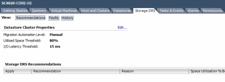
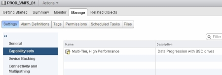
If you happen to have your vSphere cluster to be licensed with Enterprise Plus edition, you may be aware of some of the advanced storage management features it includes, such as Storage DRS and Profile-Driven Storage.

These two features work together to let you optimise VM distribution between multiple VMware datastores from capability, capacity and latency perspective, much like DRS does for memory and compute. But they have some interoperability limitations, which I want to discuss in this post.

Datastore Clusters

In simple terms, datastore cluster is a collection of multiple datastores, which can be seen as a single entity from VM provisioning perspective.

datastore_cluster

VMware poses certain requirements for datastore clustes, but in my opinion the most important one is this:

Datastore clusters must contain similar or interchangeable datastores.

In other words, all of the datastores within a datastore cluster should have the same performance properties. You should not mix datastores provisioned on SSD tier with datastores on SAS and SATA tier and vise versa. The reason why is simple. Datastore clusters are used by SDRS to load-balance VMs between the datastores of a datastore cluster. DRS balances VMs based on datastore capacity and I/O latency only and is not storage capability aware. If you had SSD, SAS and SATA datastores all under the same cluster, SDRS would simply move all VMs to SSD-backed datastores, because it has the lowest latency and leave SAS and SATA empty, which makes little sense.

Design Decision 1:

  • If you have several datastores with the same performance characteristics, combine them all in a datastore cluster. Do not mix datastores from different arrays or array storage tiers in one datastore cluster. Datastore clusters is not a storage tiering solution.

Storage DRS

As already mentioned, SDRS is a feature, which when enabled on a datastore cluster level, lets you automatically (or manually) distribute VMs between datastores based on datastore storage utilization and I/O latency basis. VM placement recommendations and datastore maintenance mode are amongst other useful features of SDRS.

storage_drs

Quite often SDRS is perceived as a feature that can work with Profile-Driven Storage to enforce VM Storage Policy compliance. One of the scenarios, that is often brought up is what if there’s a VM with multiple .vmdk disks. Each disk has a certain storage capability. Mistakenly one of the disks has been storage vMotion’ed to a datastore, which does not meet the storage capability requirements. Can SDRS automatically move the disk back to a compliant datastore or notify that VM is not compliant? The answer is – no. SDRS does not take storage capabilities into account and make decisions only based on capacity and latency. This may be implemented in future versions, but is not supported in vSphere 5.

Design Decision 2:

  • Use datastore clusters in conjunction with Storage DRS to get the benefit of VM load-balancing and placement recommendations. SDRS is not storage capability aware and cannot enforce VM Storage Policy compliance.

Profile-Driven Storage

So if SDRS and datastore clusters are not capable of supporting  multiple tiers of storage, then what does? Profile-Driven Storage is aimed exactly for that. You can assign user-defined or system-defined storage capabilities to a datastore and then create a VM Storage Policy and assign it to a VM. VM Storage Policy includes the list of required storage capabilities and only those datastores that mach them, will be suggested as a target for the VM that is assigned to that policy.

You can create storage capabilities manually, such as SSD, SAS, SATA. Or more abstract, such as Bronze, Silver and Gold and assign them to corresponding datastores. Or you can leverage VASA, which automatically assigns corresponding storage capabilities. Below is an example of a datastore connected from a Dell Compellent storage array.

datastore_capabilities

You can then use storage capabilities from the VASA provider to create VM Storage Policies and assign them to VMs accordingly.

VASA.jpg

Design Decision 3:

  • If you have more than one datastore storage type, use Profile-Driven Storage to enforce VM placement based on VM storage requirements. VASA can simplify storage capabilities management.

Conclusion

If all of your datastores have the same performance characteristics, such as a number of LUNs auto-tiered on the storage array side, then one SDRS-enabled datastore cluster is a perfect solution for you.

But if your storage design is slightly more complex and you have datastores with different performance characteristics, such as SSD, SAS and SATA, leverage Profile-Driven Storage to control VM placement and enforce compliance. Just make sure to use a separate cluster for each tier of storage and you will get the most benefit out of vSphere Storage Policy-Based Management.

RecoverPoint VE: iSCSI Network Design

March 29, 2016

recoverpointRecoverPoint is a great storage replication product, which supports Continuous Data Protection (CDP) and gives you RPO figures measured in second compared to a standard asynchronous storage-based replication solutions, where RPO is measured in minutes or even hours.

RecoverPoint comes in three flavours:

  • RecoverPoint SE/EX/CL – physical appliance for replication between VNX (RecoverPoint/SE), VNX/VMAX/VPLEX (RecoverPoint/EX) or EMC and non-EMC (RecoverPoint CL) storage arrays.
  • RecoverPoint VE – virtual edition of RecoverPoint which is installed as a VM and supports the same SE/EX/CL versions.
  • RecoverPoint for Virtual Machines – also a virtual appliance but is array-agnostic and works at a hypervisor level by replicating VMs instead of LUNs.

In this blog post we will be discussing connectivity options for RecoverPoint VE (SE edition). Make sure to not confuse RecoverPoint VE and RecoverPoint for Virtual Machines as it’s two completely different products.

VNX MirrorView ports

MirrorView is an another EMC replication solution integrated into VNX arrays. If there’s a MirrorView enabler installed, it will claim itself the first FC port and the first iSCSI port. When patching VNX iSCSI ports make sure to NOT use the ports claimed by MirrorView.

mirrorview_ports

If you use 1GbE (4-port) I/O modules you can use three ports per SP (all except port 0) and if you have 10GbE (2-port) I/O modules you can use one port per SP. I will talk about workarounds for this in the next blog post.

RPA appliance iSCSI vNICs

Each RecoverPoint appliance has two iSCSI NICs, which can be configured on either one or two subnets. If you use one 10Gb port on each SP as in the example above, then you’re forced to use one subnet. Because you obviously need at least two ports on each SP to have two networks.

If you have 1Gb modules in your VNX array, then you will most likely have two 1Gb iSCSI ports connected on each SP. In that case you can use two iSCSI subnets to reduce the number of iSCSI sessions between RPAs and a VNX.

On the vSphere side you will need to create one or two iSCSI port groups, depending on how many subnets you’ve decided to allocate and connect RPA vNICs accordingly.

rpa_iscsi

VNX iSCSI Connections

RecoverPoint clusters are deployed and connected using a special tool called Deployment Manager. It assigns all IP addresses, connects RecoverPoint clusters to VNX arrays and joins sites together.

Once deployment is finished you will have iSCSI connections created on the VNX array. Depending on how many iSCSI subnets you’re using, iSCSI connections will be configured accordingly.

1. One Subnet Example

Lets look at the one subnet topology first. In this example you have one 10Gb port per VNX SP and two ports on each of the two RPAs all on one subnet. When you right click on the storage array in Unisphere and select iSCSI > Connections Between Storage Systems you should see something similar to this.

iscsi_connections

As you can see ports iSCSI1 and iSCSI2 on RPA0 and RPA1 are mapped to two ports on the storage array A-5 and B-5. Four RPA ports are connected to two VNX ports which gives you eight iSCSI initiator records on the VNX.

iscsi_initiators

2. Two Subnets Example

If you connect two 1Gb ports per VNX SP and decide to use two subnets, then each SP will have one port on each of the two subnets. Same goes for the RPAs. Each RPA will have one vNIC connected to each subnet.

iSCSI connections will be set up a little bit differently now. Because only the VNX and RPA ports which are on the same subnet should be able to talk to each other.

iscsi_connections2

Every RPA in this example has one IP on the xxx.xxx.46.0/255.255.255.192 subnet (iSCSI A) and one IP on the xxx.xxx.46.64/255.255.255.192 subnet (iSCSI B). Similarly, ports A-10 and B-10 on the VNX are configured on iSCSI A subnet. And ports A-11 and B-11 are configured on iSCSI B subnet. Because of that, iSCSI1 ports are mapped to ports A-10/B-10 and iSCSI2 ports are mapped to ports A-11/B-11.

As we are using two subnets in this example instead of 4 RPA ports by 4 VNX ports = 16 iSCSI connections, we will have 2 RPA ports by 2 VNX ports (subnet iSCSI A) + 2 RPA ports by 2 VNX ports (subnet iSCSI B) = 8 iSCSI connections.

iscsi_initiators2

Conclusion

The goal of this post was to discuss the points which are not very well explained in RecoverPoint documentation. It’s not a comprehensive guide by any means. You can find the full deployment procedure with prerequisites, installation and configuration steps in EMC RecoverPoint Installation and Deployment Guide.

Dell Compellent iSCSI Configuration

November 20, 2015

I haven’t seen too many blog posts on how to configure Compellent for iSCSI. And there seem to be some confusion on what the best practices for iSCSI are. I hope I can shed some light on it by sharing my experience.

In this post I want to talk specifically about the Windows scenario, such as when you want to use it for Hyper-V. I used Windows Server 2012 R2, but the process is similar for other Windows Server versions.

Design Considerations

All iSCSI design considerations revolve around networking configuration. And two questions you need to ask yourself are, what your switch topology is going to look like and how you are going to configure your subnets. And it all typically boils down to two most common scenarios: two stacked switches and one subnet or two standalone switches and two subnets. I could not find a specific recommendation from Dell on whether it should be one or two subnets, so I assume that both scenarios are supported.

Worth mentioning that Compellent uses a concept of Fault Domains to group front-end ports that are connected to the same Ethernet network. Which means that you will have one fault domain in the one subnet scenario and two fault domains in the two subnets scenario.

For iSCSI target ports discovery from the hosts, you need to configure a Control Port on the Compellent. Control Port has its own IP address and one Control Port is configured per Fault Domain. When server targets iSCSI port IP address, it automatically discovers all ports in the fault domain. In other words, instead of using IPs configured on the Compellent iSCSI ports, you’ll need to use Control Port IP for iSCSI target discovery.

Compellent iSCSI Configuration

In my case I had two stacked switches, so I chose to use one iSCSI subnet. This translates into one Fault Domain and one Control Port on the Compellent.

IP settings for iSCSI ports can be configured at Storage Management > System > Setup > Configure iSCSI IO Cards.

iscsi_ports

To create and assign Fault Domains go to Storage Management > System > Setup > Configure Local Ports > Edit Fault Domains. From there select your fault domain and click Edit Fault Domain. On IP Settings tab you will find iSCSI Control Port IP address settings.

local_ports

control_port

Host MPIO Configuration

On the Windows Server start by installing Multipath I/O feature. Then go to MPIO Control Panel and add support for iSCSI devices. After a reboot you will see MSFT2005iSCSIBusType_0x9 in the list of supported devices. This step is important. If you don’t do that, then when you map a Compellent disk to the hosts, instead of one disk you will see multiple copies of the same disk device in Device Manager (one per path).

add_iscsi

iscsi_added

Host iSCSI Configuration

To connect hosts to the storage array, open iSCSI Initiator Properties and add your Control Port to iSCSI targets. On the list of discovered targets you should see four Compellent iSCSI ports.

Next step is to connect initiators to the targets. This is where it is easy to make a mistake. In my scenario I have one iSCSI subnet, which means that each of the two host NICs can talk to all four array iSCSI ports. As a result I should have 2 host ports x 4 array ports = 8 paths. To accomplish that, on the Targets tab I have to connect each initiator IP to each target port, by clicking Connect button twice for each target and selecting one initiator IP and then the other.

iscsi_targets

discovered_targets

connect_targets

Compellent Volume Mapping

Once all hosts are logged in to the array, go back to Storage Manager and add servers to the inventory by clicking on Servers > Create Server. You should see hosts iSCSI adapters in the list already. Make sure to assign correct host type. I chose Windows 2012 Hyper-V.


add_servers

It is also a best practice to create a Server Cluster container and add all hosts into it if you are deploying a Hyper-V or a vSphere cluster. This guarantees consistent LUN IDs across all hosts when LUN is mapped to a Server Cluster object.

From here you can create your volumes and map them to the Server Cluster.

Check iSCSI Paths

To make sure that multipathing is configured correctly, use “mpclaim” to show I/O paths. As you can see, even though we have 8 paths to the storage array, we can see only 4 paths to each LUN.

io_paths

Arrays such as EMC VNX and NetApp FAS use Asymmetric Logical Unit Access (ALUA), where LUN is owned by only one controller, but presented through both. Then paths to the owning controller are marked as Active/Optimized and paths to the non-owning controller are marked as Active/Non-Optimized and are used only if owning controller fails.

Compellent is different. Instead of ALUA it uses iSCSI Redirection to move traffic to a surviving controller in a failover situation and does not need to present the LUN through both controllers. This is why you see 4 paths instead of 8, which would be the case if we used an ALUA array.

References